The flash point of a volatile liquid is the lowest temperature at which it can vaporise to form an ignitable mixture in air.
Transportation regulations distinguish fuels as either flammable or combustible depending upon their flashpoint. Flammable fuels have a flashpoint below38°C. and combustible fuels have a flashpoint above 38°C. As an example, diesel fuel flashpoints range from about 50°C. to around 100°C making it relatively safe to transport and handle. Gasoline, by comparison, has a flashpoint of minus 43°C. Sparks and static electricity can easily ignite gasoline fumes.
Aviation fuels fall mainly into two categories, aviation gasoline - commonly abbreviated to “avgas” - and the variants of paraffin (kerosene) used by all gas turbine engines and loosely described as "jet fuel"
AVGAS
AVGAS is broadly similar to automotive gasoline but subject to much more rigorous quality control. The most common form of AVGAS has an octane rating of 100 - octane rating being a measure of the resistance of a fuel to pre-ignition (the chance of combustion occurring before the spark).
This flashpoint is the same as that of automotive gasoline and there is a significant danger of combustion if it is not handled carefully. Although there are many more aircraft using AVGAS than use jet fuel, they are almost exclusively light aircraft.
Jet Fuels
The most common jet fuels in use are named Jet A (U.S.) and Jet A-1 (international). They are kerosene grade fuels with a flashpoint of 38°C. Commercially available Jet B has a lower flashpoint (minus 18°C.) but it also has a much lower freezing point making it very suitable for use in extremely cold environments.
Fuels such as JP5 and JP7 have higher flashpoints and were developed to provide additional safety margins in specific military applications. All jet fuels are subject to rigorous testing for impurities and any fuel that fails such testing is diverted to ground applications.
All aviation fuels contain specified small quantities of various additives such as corrosion inhibitors, static dissipaters, and anti-freezing substances.
Diesel
A fairly recent development is light aircraft fitted with diesel engines, although this is still very much an exception.
Although the oil system of the modern gas turbine engine is varied in design and plumbing most have units which perform similar functions. In most cases a pressure pump or system furnishes oil to the engine to be lubricated and cooled.
A scavenging system returns the oil to the tank for reuse. The problem of overheating is more severe after the engine has stopped than while it is running. Oil flow which would normally have cooled the bearings has stopped. Heat stored in the turbine wheel will raise the bearing temperature much higher than that reached during operation.
Most systems will include a heat exchanger (air or fuel) to cool the oil. Many are designed with pressurized sumps. Some incorporate a pressurized oil tank. This ensures a constant head pressure to the pressure-lubrication pump to prevent pump cavitation at high altitude.
Oil consumption in a gas turbine engine is low compared to that in a reciprocating engine of equal power. Oil consumption on the turbine engine is affected by the efficiency of the seals. However, oil can be lost through internal leakage and on some engines by malfunction of the pressurizing or venting system.
Oil scaling is very important in a jet engine. Any wetting of the blades or vanes by oil vapor will encourage the accumulation of dust and dirt. A dirty blade or vane represents high friction-to-airflow. This decreases engine efficiency, and results in a noticeable decrease in thrust or increase in fuel consumption.
Since oil consumption is so low, oil tanks can be made relatively small. This causes a decrease in weight and storage problems. Tanks may have capacities ranging from l/2 to 8 gallons. System pressures may vary from 15 psig at idle to 200 psig during cold starts. Normal operating pressures and bulk temperatures are about 50 to 100 psig and 200oF, respectively.
GENERAL
In general, the parts to be lubricated and cooled include the main bearings and accessory drive gears and the propeller gearing in the turboprop. This represents again in gas turbine engine lubrication simplicity over the complex oil system of the reciprocating engine.
The main rotating unit can be carried by only a few bearings. In a piston power plant there are hundreds more moving parts to be lubricated.
On some turbine engines the oil may also be used--
To operate the servo mechanism of some fuel controls.
To control the position of the variable area exhaust-nozzle vanes.
To operate the thrust reverser.
calibrated type. With a few exceptions the lubricating system used on the modem turbine engine is of the dry-sump variety. However, some turbine engines are equipped with a combination dry- and wet-type lubrication system.
Wet-sump engines store the lubricating oil in the engine proper. Dry-sump engines utilize an external tank usually mounted on or near the engine. Although this chapter addresses dry-sump systems, an example of the wet-sump design can be seen in the Solar International T-62 engine.
In this engine the oil reservoir is an integral part of the accessory-drive gear case. An example of a combination dry-and wet-sump lubrication can be found in the Lycoming T-55-series engines.
TURBINE ENGINE DRY-SUMP LUBRICATION
In a turbine dry-sump lubrication system, the oil supply is carried in a tank mounted externally on or near the engine. With this type of system, a larger oil supply can be carried and the oil temperature can be controlled An oil cooler usually is included in a dry-sump oil system (Figure 5-l).
This cooler may be air-cooled or fuel-cooled. The dry-sump oil system allows the axial-flow engines to retain their comparatively small diameter. This is done by designing the oil tank and the oil cooler to conform to the design of the engine.
The following component descriptions include most of those found in the various turbine lubrication systems. However, not all of these components will be found in any one system. The dry-sump systems use an oil tank which contains most of the oil supply. However, a small sump usually is included on the engine to hold a supply of oil for an emergency system. The dry-sump system usually contains--
Oil pump.
Scavenge and pressure inlet strainers.
Scavenge return connection.
Pressure outlet ports.
Oil filter.
Mounting bosses for the oil pressure transmitter.
Temperature bulb connections
A typical oil tank is shown in Figure 5-2. It is designed to furnish a constant supply of oil to the engine. This is done by a swivel outlet assembly mounted inside -the tank a horizontal baffle mounted in the center of the tank, two flapper check valves mounted on the baffle, and a positive-vent system.
The swivel outlet fitting is controlled by a weighted end, which is free to swing below the baffle. The flapper valves in the baffle are normally open. They close only when the oil in the bottom of the tank rushes to the top of the tank during deceleration. This traps the oil in the bottom of the tank where it is picked up by the swivel fitting A sump drain is located in the bottom of the tank. The airspace is vented at all times.
All oil tanks have expansion space. This allows for oil expansion after heat is absorbed from the bearings and gears and after the oil foams after circulating through the system. Some tanks also incorporate a deaerator tray.
The tray separates air from the oil returned to the top of the tank by the scavenger system. Usually these deaerators are the "can" type in which oil enters a tangent. The air released is carried out through the vent system in the top of the tank.
Inmost oil tanks a pressure buildup is desired within the tank. This assures a positive flow of oil to the oil pump inlet. This pressure buildup is made possible by running the vent line through an adjustable check-relief valve.
The check-relief valve normally is set to relieve at about 4 psi pressure on the oil pump inlet.
There is little need for an oil-dilution system. If the air temperature is abnorrnally low, the oil may be changed to a lighter grade. Some engines may provide for the installation of an immersion-type oil heater.
TURBINE ENGINE WET-SUMP LUBRICATION
In some engines the lubrication system is the wet-sump type. Because only a few models of centrifugal-flow engines are in operation, there are few engines using a wet-sump type of oil system. The components of a wet-sump system are similar to many of a dry-sump system. The oil reservoir location is the major difference. The reservoir for the wet-sump oil system may be the accessory gear case, which consists of the accessory gear casing and the front compressor bearing support casing. Or it may be a sump mounted on the bottom of the accessory case. Regardless of configuration reservoirs for wet-sump systems are an integral part of the engine and contain the bulk of the engine oil supply. The following components are included in the wet-sump reservoir:
A bayonet-type gage indicates the oil level in the sump.
Two or more finger strainers (filters) are inserted in the accessory case for straining pressure and scavenged oil before it leaves or enters the sump. These strainers aid the main oil strainer.
A vent or breather equalizes pressure within the accessory casing.
A magnetic drain plug may be provided to drain the oil and to trap any ferrous metal particles in the oil. This plug should always be examined closely during inspections. The presence of metal particles may indicate gear or bearing failure.
A temperature bulb and an oil pressure fitting may be provided.
This system is typical of all engines using a wet-sump lubrication system. The bearing and drive gears in the accessory drive casing are lubricated by a splash system. The oil for the remaining points of lubrication leaves the pump under pressure.
It passes through a filter to jet nozzles that direct the oil into the rotor bearings and couplings. Most wet-sump pressure systems are variable-pressure systems in which the pump outlet pressure depends on the engine RPM.
The scavenged oil is returned to the reservoir (sump) by gravity and pump suction. Oil from the front compressor bearing in the accessory-drive coupling shaft drains directly into the reservoir. Oil from the turbine coupling and the remaining rotor shaft bearings drains into a sump. The oil is then pumped by the scavenge element through a finger screen into the reservoir.
OIL SYSTEM COMPONENTS
The oil system components used on gas turbine engines are--
Tanks.
Pressure pumps.
Scavenger pumps.
Filters.
Oil coolers.
Relief valves.
Breathers and pressurizing components.
Pressure and temperature gages lights.
Temperature-regulating valves.
Oil-jet nozzle.
Fittings, valves, and plumbing.
Chip detectors.
Not all of the units will be found in the oil system of any one engine. But a majority of the parts listed will be found in most engines.
Oil Tanks
Tanks can be either an airframe or engine-manufacturer-supplied unit. Usually constructed of welded sheet aluminum or steel, it provides a storage place for the oil. In most engines the tank is pressurized to ensure a constant supply of oil to the pressure pump. The tank can contain--
Venting system.
Deaerator to separate entrained air from the oil.
Oil level transmitter or dipstick.
Rigid or flexible oil pickup.
Coarse mesh screens.
Various oil and air inlets and outlets.
Pressure Pumps
Both gear- and Gerotor-type pumps are used in the lubricating system of the turbine engine. The gear-type pump consists of a driving and a driven gear. The engine-accessory section drives the rotation of the pump. Rotation causes the oil to pass around the outside of the gears in pockets formed by the gear teeth and the pump casing. The pressure developed is proportional to engine RPM up to the time the relief valve opens. After that any further increase in engine speed will not result in an oil pressure increase. The relief valve may be located in the pump housing or elsewhere in the pressure system for both types of pumps. The Gerotor pump has two moving parts: an inner-toothed element meshing with an outer-toothed element. The inner element has one less tooth than the outer. The missing tooth provides a chamber to move the fluid from the intake to the discharge port. Both elements are mounted eccentrically to one another on the same shaft.
Scavenger Pumps
These pumps are similar to the pressure pumps but have a much larger total capacity. An engine is generally provided with several scavenger pumps to drain oil from various parts of the engine. Often one or two of the scavenger elements are incorporated in the same housing as the pressure pump (Figure 5-3).
Different capacities can be provided for each system despite the common driving shaft speed. This is accomplished by varying the diameter or thickness of the gears to vary the volume of the tooth chamber. A vane-type pump may sometimes be used.
Oil Filters and Screens or Strainers
To prevent foreign matter from reaching internal parts of the engine, filters and screens or stainers are provided in the engine lubricating system.
The three basic types of oil filters for the jet engine are the cartridge screen-disc and screen (Figures 5-4, 5-5 and 5-6).
The cartridge filter is most commonly used and must be replaced periodically. The other two can be cleaned and reused.
In the screen-disc filter there are a series of circular screen-type filters. Each filter is comprised of two layers of mesh forming a chamber between mesh layers.
The filters are mounted on a common tube and arranged to provide a space between each circular element.
Lube oil passes through the circular mesh elements and into the chamber between the two layers of mesh.
This chamber is ported to the center of a common tube which directs oil out of the filter. Screens or strainers are placed at pressure oil inlets to bearings in the engine.
This aids in preventing foreign matter from reaching the bearings.
To allow for oil flow in the event of filter blockage, all filters incorporate a bypass or relief valve as part of the filter or in the oil passages.
When the pressure differential reaches a specified value (about 15 to 20 psi), the valve opens and allows oil to bypass the filter. Some filters incorporate a check valve. This prevents reverse flow or flow through the system when the engine is stopped Filtering characteristics vary, but most filters will stop particles of approximately 50 microns.
Magnetic Chip Detector
One or more magnetic chip detectors are installed on gas turbine engines. They are used to detect and attract ferrous material (metal with iron as its basic element) which may come from inside the engine. This ferrous material builds up until it bridges a gap. Whenever there is a requirement, the chip detectors may be collected and analyzed to determine the condition of the engine. Most engines utilize an electrical chip detector, located in the scavenger pump housing or in the accessory gearbox. Should the engine oil become contaminated with metal particles, the detector will catch some of them. This causes the warning light on the caution panel to come on. Tubing, Hose, and Fittings Tubing, hose, and fittings are used throughout the lubricating system. Their purpose is to connect apart into a system or to connect one part to another to complete a system. Oil Pressure Indicating System In a typical engine oil pressure indicating system the indicator receives inlet oil pressure indications from the oil pressure transmitter and provides readings in pounds per square inch Electrical power for oil pressure indicator and transmitter operation is supplied by the 28-volt AC system. Oil-Pressure-Low Caution Light Most gas turbine engine lubricating systems incorporate an engine oil-pressure-low caution light warning device into the system for safety purposes. The light is connected to a low-pressure switch. When pressure drops below a safe limit, the switch closes an electrical circuit causing the caution light to burn. Power is supplied by the 28-volt DC system. Oil Temperature Indicating System In a typical engine oil temperature indicating system, the indicator is connected to and receives temperature indications from an electrical resistance-type thermocouple or thermobulb. These are located in the pressure pump oil inlet side to the engine. Power to operate this circuit is supplied by the 28-volt DC system. Oil Coolers The oil cooler is used to reduce oil temperature by transmitting heat from the oil to another fluid usually fuel. Since the fuel flow through the cooler is much greater than the oil flow, the fuel is able to absorb a considerable amount of heat. This reduces the size and weight of the cooler. Thermostatic or pressure-sensitive valves control the oil temperature by determining whether the oil passes through or bypasses the cooler. Oil coolers are also cooled by air forced through them by a blower/fan. Breathers and Pressurizing Systems Internal oil leakage is kept to a minimum by pressurizing the bearing sump areas with air that is bled off the compressor (Figure 5-7). The airflow into the sump minimizes oil leakage across the seals in the reverse direction.
The oil scavenge pumps exceed the capacity of the lubrication pressure pump They are capable of handling considerably more oil than actually exists in the bearing sumps and gearboxes. Because the pumps area constant-displacement type, they make up for the lack of oil by pumping air from the sumps. Large quantities of air are delivered to the oil tank. Sump and tank pressures are maintained close to one another by a line which connects the two. If the sump pressure exceeds the tank pressure, the sump vent check valve opens, allowing the excess sump air to enter the oil tank. The valve allows flow only into the tank; oil or tank vapors cannot back up into the sump areas. Tank pressure is maintained little above ambient. The scavenge pumps and sump-vent check valve functions result in relatively low air pressure in the sumps and gearboxes. These low internal sump pressures allow air to flow across the oil seals into the sumps. This airflow minimizes lube oil leakage across the seals. For this reason it is necessary to maintain sump pressures low enough to ensure seal-air leakage into the sumps. Under some conditions, the ability of the scavenge pumps to pump air forms a pressure low enough to cavitate the pumps or cause the sump to collapse. Under other conditions, too much air can enter the sump through worn seals. If the seal leakage is not sufficient to maintain proper internal pressure, check valves in the sump and tank pressurizing valves open and allow ambient air to enter the system. Inadequate internal sump and gearbox pressure may be caused by seal leakage. If that occurs, air flows from the sumps, through the sump-vent check valve, the oil tank, the tank and sump pressurizing valves to the atmosphere. Tank pressure is always maintained a few pounds above ambient pressure by the sump and tank pressurizing valve. The following addresses two types of lubrication systems used in the Army today: the General Electric T-701 turboshaft engine and the International/Solar T-62-series engine.
TYPICAL OIL SYSTEM FOR T-701
The lubrication system in the T-700-GE-701 engine distributes oil to all lubricated parts (Figure 5-8). In emergencies it supplies an air-oil mist to the main shaft bearings in the A- and B-sumps. The system is a self-contained, recirculating dry-sump system. It consists of the following subsystems and components:
Oil supply and scavenge pump.
Seal pressurization and sump venting.
Emergency lube system.
Oil filtration and condition monitoring.
Tank and air-oil cooler.
Oil cooler.
Oil pressure monitoring.
Cold oil-relief and cooler-bypas valves.
Chip detector.
Integral accessory gearbox
Lube Supply System
The oil tank, integral with the mainframe, holds approximately 7.3 quarts of oil (Figure 5-9). This is a sufficient quantity to lubricate the required engine parts without an external oil supply. The tank is filled using a 3-inch, gravity-fill port on the right-hand side. Visual indication of oil level is supplied by a fluid level indicator installed on each side of the tank. A coarse pickup screen located near the tank bottom keeps sizable debris form entering the lube supply pump inlet. A drain plug is located at the bottom of the tank. Oil from the pickup screen enters a cast passage in the mainframe. It is then conducted to the top of the engine to a point beneath the lube supply pump. A short connector tube transfers the oil from the mainframe to the accessory gearbox pump inlet port. The connector tube contains a domed, coarse-debris screen. The screen keeps foreign objects out of the passage when the accessory module is not installed on the mainframe. Oil flows through the connector tube to the pump inlet. There it enters the pump tangentially in alignment with pump rotational direction. The lube supply pump, a Geroter-type pumping element assembly, is comprised of an inner and outer element. The element assembly is located adjacent to the drive spline end of the pump. Six scavenge elements are also located in tandem on the common drive shaft. The stack of pump elements is retained in a cast tubular hosing having an integral end plate. The complete pump slides into a precision bore in the gearbox casing. Oil from the supply pump flows to the lube filter inlet and through the filter, a 3-micron filter element. Oil flow passes from outside to inside of the filter element. It then passes through the open bore of the bypass valve and into the gearbox outlet passage. Bypass valve opening occurs when filter differential pressure unseats a spring-loaded poppet from its seat. the filter bowl contains an impending bypass warning button which will provide an indication for filter servicing. An electrical bypass sensor for cockpit indication of filter bypass tits into an AGB boss adjacent to the lube filter. A differential pressure of 60-80 psi across the filter will actuate this sensor. A spring-loaded poppet-type, cold oil relief valve is incorporated in this system. This valve prevents excessive supply pressure during cold starts when high oil viscosity creates high line pressures. Cracking pressure is set for 120-180 psid and reset is 115 psid minimum. When open, apart of the lube flow is discharged into the AGB where churning in the gears will assist in reducing warm-up time. Oil leaving the filter branches in three directions. It goes to the to of the emergency oil reservoirs in the A and B-sumps, the AGB, and C-sump jets.
Scavenge System. After the oil has lubricated and cooled the parts, the scavenge system returns it to the oil tank (Figure 5-10). In addition, fuel-oil and air-oil coolers and a chip detector are located in the scavenge return path.
Scavenge Inlet Screens. Each scavenge pump inlet is fitted with a relatively coarse screen (Figure 5-11).
This screen is designed to protect the pumps from foreign object damage and to provide for fault isolation. Scavenge oil (and air) enters the bore of each screen axially on the open inner end.
It exits into a cast annulus which discharges directly into the scavenge pump inlet.
These screens may be removed for inspection if chip generation is suspected
Scavenge pumps. Six scavenge pumps are in line with the lube supply pump on a common shaft (Figure5-10). Positioning of the pump elements is determined by these factors:
The lube supply element is placed in the least vulnerable location and isolated from scavenge elements at one end.
The B-sump element is placed at the other end of the pump to help isolate it from the other scavenge elements. This element is the only one with an elevated inlet pressure.
Pump windmilling experience on other engine scavenge pumps shows that adjacent pumps tend to cut each other off due to inter element leaks at very low speed Therefore, the two A-sump elements are placed adjacent, as are the three C-sump elements, to reduce the possibility of both elements in a sump being inoperative simultaneously.
Porting simplification for the gearbox coring determines relative positions of A- sump, B-sump, and C-sump elements.
Scavenge Discharge Passage. The common discharge of all six scavenge pumps is cast into the gearbox at the top of the pump cavity. Top discharge facilitates priming by clearing air bubbles and by wetting all pumping elements from the discharge of first pumps to prime. The discharge cavity is tapered to enlarge as each pump enters the flow steam.
This keeps discharge velocity relatively constant. It also tends to avoid air traps which could short-circuit pumping at windmilling speeds. This discharge plenum flows into the core to the chip detector. Flow leaving the chip detector passes to the fuel-oil cooler in series with the air-oil cooler. To promote faster warm-up and guard against plugged coolers, a bypass valve is provided which bypasses both coolers.
Air-oil cooling is an integral part of the mainframe casting. Scavenge oil enters a manifold at the tank top. It then flows in a serpentine fashion in and out through the hollow scroll vanes and box-sectioned hub. Air for the particle separator is pulled across the vanes by the scavenge air blower providing the oil cooling process. Exit from the air-oil cooler is through three holes at the top of the tank. These outlets disperse the oil over the tank surfaces on both sides to settle in the tank. The oil tank vents to the AGB.
Emergency Oil System
The T-700-GE-701 engine is designed to have two oil jets to provide each main bearing with oil for lubricating and cooling (Figure 5-12).
In addition to being designed for normal engine operation, the system provides for operation if the normal oil supply from the primary system is interrupted. The AGB and C-sump components can continue to operate at least 6 minutes with residual oil present. The No. 4 bearing in the B-sump and the bearings and gears in the A-sump are provided with emergency air-oil mist systems located in each sump. The emergency oil system forms part of the normal full-time lubrication system and incorporates one full set of main bearing oil jets operating in parallel with the primary jets. The dual-jet system also provides redundancy to minimize the effect of oil jet plugging. A small reservoir, curved to tit the A- and B-sumps, retains a sufficient amount of oil to provide air-oil mist when normal lubrication is interrupted The total sump oil supply is fed into the reservoir at the top. Top feed prevents reservoir drainage if the supply line is damaged. Primary oil jets, squeeze film damper, and uncritical lube jets are connected to a standpipe at the top of the tank. Secondary or emergency jets are similarly connected to the lowest point in the tank. Secondary jets are only located at points where lubrication is vital for short-duration emergency operation. Each secondary oil jet has a companion air jet or air source which flows over the end of the oil jet and impinges on the lubricated part. The air jets aspirate oil mist when normal oil supply pressure is lost. They are pressurized from the seal pressurization cavities and operate continuously with no valving required.
Component Description
The oil filter (Figure 5-13) consists of three sub assemblies:
Filter element.
Bowl and impending bypass indicator.
Bypass valve and inlet screen.
Filter Element. Media used in this filter are high-temperature materials containing organic and inorganic fibers. The layered media are faced on both sides with stainless steel mesh. This mesh provides mechanical support to resist collapse when pressure loads become high. Pleating of the faced media adds surface area and mechanical rigidity. A perforated steel tube in the bore also adds rigidity and retains the circular shape of the element. The media and support tube are epoxy-bonded to formed sheet metal and caps. These end caps include an O-ring groove which seals inlet to outlet leak paths at each end. Filtration level selected is 100 percent of all particles three microns or larger and is disposable when saturated with debris. Support of the filter element is provided by the bypass valve on one end and the impending bypass indicator on the other. The indicator end has a spring-loaded sleeve which restrains the filter axially.
Bowl and Bypass Indicator. An aluminum bowl houses the element and contains the impending bypass indicator at the end. Mounting is horizontal to fit the space available and provide ready access for servicing Impending bypass indication is provided by a small unit which is part of the bowl assembly. The indicator is installed from the inside of the bowl. It is retained in place with an external retaining ring. Basic mechanics of operation are as follows:
Different pressure between filter inlet and outlet acts to move a piston against a spring at 44 to 60 psi.
Piston contains a magnet which normally attracts a red button assembly and holds it seated against its spring. When the piston moves, the button is released. It extends 3/16 inch to visually indicate an impending bypass condition.
Button is physically reattained from tripping by a cold lockout bimetallic latch if temperature is less than 100 to 130°F. This prevents a false trip during cold starts.
As the button is released, a small spring-loaded ball also moves out of position to latch the button and block reset. The internal piston assembly automatically resets on shutdown; however, the indicator remains latched out.
After removing the filter element and the bowl from the gearbox, a spring-loaded sleeve around the indicator moves aft and pulls the piston assembly to a tripped position. This causes the button to trip if operation is attempted with no filter in the bowl.
To react the indicator, the bowl is held vertically so the button latch ball can roll out of the latched position. The button is then manually reset.
If the bowl is reassembled with no filter, the indicator will trip when the temperature exceeds the 100 to 130°F lock-out level. The internal latch mechanism prevents resetting the button without disassembling the bowl. Resetting must be done with the bowl removed from the accessory gearbox and held vertically, button up, to release the latch.
Oil Filter Bypass Sensor. The oil filter bypass sensor is a differential-pressure switch which senses filter inlet minus outlet pressure. The sensor consists of a spring-loaded piston which moves aft at high filter differential pressure (60 to 80 psi) and magnetically releases a microswitch lever. The switch is in a sealed cavity separated from the oil and is wired to a hermetically sealed electrical connector. The switch connects 28-VDC aircraft power when tripped and reopens the circuit at 15 psi minimum differential No latch is used in the sensor so resetting is automatic. Also, there is no cold lockout. The pilot will be informed of filter bypassing during cold start warm-ups. Sensor tolerance range is set slightly below the tolerance range of bypass valve cracking pressure. Therefore, bypassing will not occur without pilot warning. The impending bypass indicator will show need-to-change filter elements. This sensor provides backup warning if maintenance action is not taken.
Lubrication and Scavenge Pump. The lube and scavenge pump is a Gerotor-type pump of cartridge design, located on the forward side of the accessory gearbox (refer back to Figure 5-10). It fits into a precision bore in the gearbox casing. The Gerotor-type pump was chosen because of its wear resistance and efficiency. Gerotor elements are similar to male gear inside a female (internal) gear with one less tooth on the inner member. The inner Gerotors are keyed to the drive shaft, and the outer Gerotors are pocketed in individual eccentric rings. AS the assembly rotates, oil is drawn into an expanding cavity between teeth on one side. The oil is expelled when the cavity contracts approximately 180° away. Inlet and discharge ports are cast into the port plates. They are shaped and positioned to fill and empty at proper timing for maximum volumetric efficiency and resistance to inlet cavitation. There are seven different elements in the pump from the spline end forward. They are the lube supply element, C-sump cover, C-sump aft, C-sump forward, A-sump forward, A-sump aft, and B-sump Delta scavenge elements. The port plate eccentric rings and Gerotors are assembled into a surrounding concentric aluminum tubular housing The housing maintains all elements in proper alignment. The oil suction and discharge pas-sages from the Gerotors are brought radially through the housing. They match the appropriate locations of the mating passages in the engine gearbox casing. The entire stack of port plates is retained in the housing with the retaining rings at the spline end. The outermost end of the housing has an integrally cast cover. The cover bolt holes are arranged to orient the pump assembly in the gearbox housing during installation.
Cold Oil Relief Valve. The cold oil relief valve protects the oil supply system from overpressure during cold starts (refer back to Figure 5-9). It is a conventional poppet-type valve with a cracking pressure of 120-180 psi. Valve tolerances are held sufficiently close to achieve the desired sacking pressure without adjustment shims or selective fitting of parts. The valve includes a No. 10-32 threaded hole on the outside. This allows for the use of a bolt as a pulling handle during valve removal from the AGB.
Oil Cooler. The fuel-oil cooler is a tube and shell design (Figure 5-14). It cools the combined output of the scavenge discharge oil that is ported through gearbox-cored passages to the cooler. The cooler is mounted adjacent to the fuel-boost pump on the forward side of the gearbox. Oil and fuel porting enter on the same end via face porting to the gearbox. Fuel is used as the coolant. It is provided to the cooler via the boost pump, fuel filter, and hydromechanical control unit. A counterparallel flow, miltipass cooler design is used to minimize pressure drop while obtaining maximum cooler effectiveness. Fuel flows through the tubes, while the oil flows over the tubes resulting in the counterparallel flow arrangement.
Oil Cooler Bypass Valve. Design of the oil cooler bypass valve is identical to the cold oil relief valve with an exception (refer back to Figure 5-9). A lighter spring is utilized to obtain a lower cracking pressure of 22-28 psi. Housing modifications prevent inadvertent interchange with the cold oil relief valve.
Chip Detector. The chip detector in the common scavenge line is the engine diagnostic device most likely to provide first warning of impending part failure (Figure 5-15).
The chip detector magnetically attracts electrically conductive ferrous chips. The chips bridge the gap between the detector's electrodes and close a circuit in series with the aircraft cockpit indicator (warning light). The chip detecting gap has a magnetic field induced in tapered pose pieces at each end of a cylindrical permanent magnet. A single ferrous chip 0.090 inch in length or longer will be indicated if magnetically attracted to bridge the pole pieces. The local magnetic field is intense at the gap and tends to orient particles in the bridging direction. Smaller particles tend to form chains until the pole pieces are bridged Non conductive particles greater than 0.015 inch are trapped inside the screen for visual examination. Smaller particles will be found either in the lube tank or in the lube supply filter. The detector housing pushes into the accessory gearbox It is retained by two captive bolts used in common with other accessories. Self-locking inserts in the gearbox ensure retention of these bolts if assembly torque is improperly low.
Venting System
A-Sump. The A-sump centervent handles air-oil separation and overboard venting from these sources:
A-sump seals and emergency air system.
Scavenge pumped air from the lube tank.
Accessory gearbox vent (no air sources).
B-sump centervent flow which passes through the intershaft seal.
Path of this vent is into the bore of the power turbine shaft and torque-reference tube and out the aft end of the engine through the C-sump cover. The centrifugal air-oil separator vent holes in the power turbine shaft are located under the forward end of the high-speed shaft. Wind age from PTO gear lock nut wrenching slots assists in turning oil back into the sump. Air from the sump and inter shaft seal flows inward radially through these holes in the power turbine shaft. The air must flow forward in the annuls between the power turbine shaft and the torque-reference tube. Movement of air is blocked by a standoff ring on the reference tube OD. The forward axial passage of the air centrifuges oil droplets outward to the bore of the power turbine shaft. They either flow back into the sump at the center vent or at small weep holes forward of the PT shaft spline. Dried air then exits through multiple rows of holes in the reference tube and out the aft C-sump cover. Some remaining oil in this air is spun into the C-Sump if it has condensed in transit. Any additional accumulated oil is then scavenged through the C-sump cover.
B-Sump. A center vent on the forward side of the No. 4 bearing accommodates air entering the sump at the labyrinth seals at each end Two rows of small holes are drilled in a radially thickened section of the forward seal runner. Use of many small holes increases the surface area of metal in contact with exiting oil droplets. These small holes also reduce effective window area for any droplets which may have a trajectory aimed directly at the holes. After the air is inside these holes, it follows a tortuous path through additional rows of holes in the turbine shaft and compressor rear shaft. The air then enters the annuls between the high-and low-speed shafts. In doing this, remaining oil is spun back into the sump. About 70 percent of B-sump center vent flow moves forward through the bore of the compressor tie bolt and inter shaft seal. It exits at the A-sump center vent. Oil weep holes are provided near the aft end of the compressor tie bolt. These weep holes keep oil out of the rotor by returning it to the sump. A rotor seal is provided hereto keep any wee page out of the seal air. This airflow keeps the compressor tie bolt relatively cool and uniformly clamped. The remaining 30 percent of B-sump center vent air joins the inner balance piston seal leakage flow. It exits aft under the gas generator turbine wheels. C-Sump. Center venting the C-sump is a passage between the aft end of the PT shaft and a stationary standpipe built into the C-sump cover. Wind age at the torque and speed-sensor teeth and in the annuls between the reference tube and the standpipe will return oil droplets to the sump. Weep holes are provided through the reference tube, shaft, and bearing spacer to allow oil from C-or A-sumps to enter the C-sump. C-sump cover scavenging through the C-sump housing removes remaining oil accumulation from the center venting process during locked PT rotor operation and normal operation. Oil Tank. After being routed through air-oil cooler passages into the oil tank, air from the scavenge pumps flows down the radial drive shaft passage (Axis A) into the A-sump. Center venting occurs after air enters the A-sump. Accessory Gearbox. The accessory gearbox is vented through the Axis A pad via the mainframe oil tank and eventually through the A-sump. The AGB, tank, and A-sump essentially operate at the same pressure levels since they are interconnected.
LUBRICATION SYSTEM FOR T-62
The lubrication system consists of--
Pump.
Internal oil passages.
Oil filter assembly.
Filter bypass relief valve.
Pressure switch (mounted externally).
Oil jet ring.
Sump.
The oil filter cavity, oil passages, and oil sump are built into the reduction drive housing. Two oil separator plates are installed on the accessory drive gear. Lubrication system capacity is 3 quarts and is a wet-sump system. Oil is drawn out of the sump into the pump housing. The oil is carried between the pump gear teeth and pump housing wall. It is then forced through drilled passages to the oil filter housing. Oil under pump pressure enters the bottom of the filter housing and passes through the filter element (from outside to inside). It then flows out the housing through a passage in the filter element cap. A relief valve in the filter element cap unseats at a differential pressure of 15 to 25 psi. This allows oil to flow from outside the filter element, through a passage in the filter element cap, to the filter outlet passage. If the filter element becomes clogged, the valve will open and allow oil to bypass the filter element. From the filter, oil is forced into a passage to the system relief valve and to four oil jets. The oil jet ring, which encircles the high-speed input pinion, contains three of these jets. It sprays oil to the points where the high-speed input pinion meshes with the three planetary gears. One jet directs a spray between the end of the output shaft and the high-speed pinion to create a mist for lubrication of the rotor shaft bearings. The remaining gears and bearings are lubricated by air-oil mist created when oil strikes the planetary gears and high-speed pinion. System pressure is maintained at 15 to 25 psi by a system relief valve. The valve regulates pressure by bypassing excessive pressure directly into the reduction drive housing. The bypassed oil strikes the inside surface of the air inlet housing, aiding in cooling the oil. Bypassed oil returns to the sump by gravity flow through an opening in the bottom of the planet carrier. The normally open contacts of the low oil pressure switch close on increasing oil pressure at 5 to 7 psi. When the switch contacts close, the low oil pressure circuit is deenergized. At rated engine speed a drop in oil pressure below 5 to 7 psi will open the low oil pressure switch contacts. Through electrical circuitry, the drop in oil pressure will also close the main fuel solenoid valve and shut down the engine.
The following are the types of fluid commonly used in aircraft operating today, some of them remain in use in aging aircraft and so may become obsolete as aircraft types are withdraw from service.
Due to the differences in composition, hydraulic fluids may not be mixed, even those of the same base type.During the design stage, aircraft manufacturers will select a fluid appropriate to the system or aircraft and specify this in maintenance manuals, this is then the only permissible fluid to be used for that aircraft.
Should cross contamination with other fluids occur, such as may be caused by filling with the incorrect fluid type, then the whole system must be drained and flushed outprior to system operation.
The manufacturer will usually give advice in the aircraft maintenance manuals regarding what action is required with regard to rubber seals etc. should the system become contaminated in this way.
DTD 900/4081
A natural Castor based oil, golden yellow to brown in colour, it must be used with natural rubber seals.
It is flammable, strips paint and attacks synthetic rubber.
It is toxic in a fine spray mist.
Aeroshell 41/Mil-H-5606/
Def Stan 91-48
A mineral based oil, red in colour, must be used with synthetic rubber seals. It is flammable and attacks natural rubber.
Its density and lubricating properties vary with temperature.
Skydrol 500B/Mil-H-8446
A synthetic, phosphate-ester based oil, purple in colour, its major advantage is that it is fire resistant.
It will strip paint and attacks both natural and synthetic rubber.
Slightly heavier than water, it does however, have a very broad range of operating temperatures.
Seals for use with synthetic oils are made from Butyl, Ethylene, Propylene, and Teflon.
It will absorb moisture from the atmosphere if exposed to it.
Skydrol 500B-4
An improved type, which has the same properties but provides more resistance to wear and erosion of orifices and valve lands.
Skydrol LD-4
A special low-density version, it provides a weight saving of approximately 5% on a volume basis, compared to other Skydrol types.
Lightning is a discharge of electricity between highly charged clouds, or between a charged cloud and the ground.
If an aircraft is operating in the vicinity of such clouds, a discharge may strike the aircraft.
This may happen during flight or on the ground and can result in very high voltages and currents passing through the aircraft structure.
All separate parts of an aircraft are electrically bonded together to conduct a lightning strike away from areas where damage may hazard the aircraft, eg fuel tanks or flying controls.
Metallic wires or filaments within the composite structure, allowing for conductivity, may protect composite or non-metallic structures such as wing tips and nosecones.
The use of metallic wires or filaments within nosecones radomes or dielectric panels is a design feature that will not interfere with radio and radar efficiency and effect transmissions.
Lightning strikes may have two effects on an aircraft:
• Strike damage where the discharge enters the aircraft. • Static discharge damage after the strike.
Strike damage is usually found at the wing tips, leading edges of wings and tail unit, and at the fuselage nose.
On some aircraft types, other areas may be more likely to be struck by lightning; Information on this should be obtained from the aircraft maintenance manual.Static discharge damage is usually found at wing tips, trailing edges and antenna.
Strike damage is usually in the form of small circular holes and pinholes in the exterior skin. These may be in clusters or spread out over a wide area.Burning or discoloration, blisters or holes may accompany them on radomes and cracks in glass fibre.Static discharge damage is usually in the form of local pitting and burning at trailing edges.
The name GAS TURBINE means exactly what it says. A turbine type engine that is operated by gas rather than one operated, for instance, by steam or water. The gas which operates the turbine is the product of the combustion that take place when a suitable fuel is mixed and burned with the air passing through the engine.
Leonado Da Vinci
Da Vinci described the chimney jack, as the hot air from the fire rose, it was made to pass through a series of fan blades and through a series of gears, turn a roasting.
Sir Isaac Newton
Sir Isaac Newton formulated the laws of MOTION on which all devices utilizing the jet propulsion theory are based. The vehicle illustrated in the picture below , called Newton's wagon , applied the principle of jet propulsion . It is though that Jacob Gravesand , a Dutchman , actually designed this " horseless carriage", and that Isaac Newton may have only supplied the idea. The wagon consisted of a large boiler mounted on four wheels. Steam generated by fire built below the boiler was allowed to escape through a nozzle facing rearward. The speed of vehicle was controlled by a steam cock located in the nozzle.
HISTORY
England
Sir Frank Whittle :
Whittle is considered by many to be the father of the jet engine. In 1930 Frank Whittle submitted his patent application for a jet aircraft engine.
The first Whittle engine was called the Power Jet W.1, after its manufacturer. It flew in the British Gloster G.40 on May 15, 1941 with W 1 Whittle engine installed.
Germany
VON OHAIN
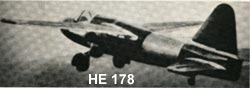
At the same time, von Ohain in Germany had been at work on the development of a jet engine for aircraft. He built and ran his first demonstration engine in 1937. His first flight engine was the HES 3B which used on HE178 and flew on August 27,1939.
The Whittle and the von Ohain engines led to successful jet-powered fighter aircraft by the end of World War II , the Messerschmitt Me262 that was used by German Air Force.
It might be note that the early English production jet engine used centrifugal compressor where as the production engine in Germany employed the more advanced axial flow compressor.
America
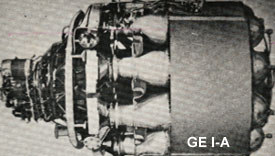
America was a late-comer to the jet-propulsion field and with the help of British Government , the General Electric Corporation was awarded the contract to built W.1 an American Version. The first jet engine airplane in America was made in October 1942, in Bell XP-59A . The two General Electric I-A engines used in this airplane, the I-A engine was rated at about 1300 lb of thrust. In late 1941 , NAVY awarded the contract to Westinghouse . Westinghouse engineers designed an engine with an axial compressor and an anular combustion chamber. Shortly thereafter, several other companies began to design and produce gas turbine engines.
ENGINE TYPES and APPLICATIONS
Introduction
Most of modern passenger and military aircraft are powered by gas turbine engines, which are also called jet engines. There are several types of jet engines, but all jet engines have some parts in common . Aircraft gas turbine engines can be classified according to (1) the type of compressor used and (2) power usage produces by the engine.
Compressor types are as follows 1. Centrifugal flow
2. Axial flow
3. Centrifugal-Axial flow.
Power usage produced are as follows 1. Turbojet engines
2. Turbofan engines.
3. Turboshaft engines.
Centrifugal Compressor Engines
Centrifugal flow engines are compress the air by accelerating air outward perpendicular to the longitudinal axis of the machine. Centrifugal compressor engines are divided into Single-Stage and Two-Stage compressor. The amount of thrust is limited because the maximum compression ratio.
Principal Advantages of Centrifugal Compressor
1. Light Weight 2. Simplicity 3. Low cost.
Axial Flow Compressor Engines
Axial flow compressor engines may incorporate one , two , or three spools (Spool is defined as a group of compressor stages rotating at the same speed) . Two spool engine , the two rotors operate independently of one another. The turbine assembly for the low pressure compressor is the rear turbine unit . This set of turbines is connected to the forward , low pressure compressor by a shaft that passes through the hollow center of the high pressure compressor and turbine drive
Adventages and Disadventages
Adventages:
Most of the larger turbine engines use this type of compressor because of its ability to handle large volumes of airflow and high pressure ratio. Disadventages:
More susceptable to foreign object damage , Expensive to manufacture , and It is very heavy in comparision to the centrifugal compressor with the same compression ratio.
Axial-Centrifugal Compressor Engine
Centrifugal compressor engine were used in many early jet engines , the efficiency level of single stage centrifugal compressor is relatively low .
The multi-stage compressors are some what better , but still do not match with axial flow compressors.
. Some small modern turbo-prop and turbo-shaft engines achieve good results by using a combination axial flow and centrifugal compressor such as PT6 Pratt and Whitney of canada which very popular in the market today and T53 Lycoming engine.
Characteristics and Applications
The turbojet engine :
Turbojet engine derives its thrust by highly accelerating a mass of air , all of which goes through the engine.
Since a high " jet " velocity is required to obtain an acceptable of thrust, the turbine of turbo jet is designed to extract only enough power from the hot gas stream to drive the compressor and accessories .
All of the propulsive force (100% of thrust ) produced by a jet engine derived from exhaust gas.
The turboprop engine :
Turboprop engine derives its propulsion by the conversion of the majority of gas stream energy into mechanical power to drive the compressor , accessories , and the propeller load.
The shaft on which the turbine is mounted drives the propeller through the propeller reduction gear system .
Approximately 90% of thrust comes from propeller and about only 10% comes from exhaust gas.
The turbofan engine :
Turbofan engine has a duct enclosed fan mounted at the front of the engine and driven either mechanically at the same speed as the compressor , or by an independent turbine located to the rear of the compressor drive turbine .
The fan air can exit seperately from the primary engine air , or it can be ducted back to mix with the primary's air at the rear .
. Approximately morethan 75% of thrust comes from fan and less than 25% comes from exhaust gas.
The turboshaft engine :
Turboshaft engine derives its propulsion by the conversion of the majority of gas stream energy into mechanical power to drive the compressor , accessories , just like the turboprop engine
but The shaft on which the turbine is mounted drives something other than an aircraft propeller such as the rotor of a helicopter through the reduction gearbox .
The engine is called turboshaft.
ENGINE THEORY
OPERATION
The jet engines are essentially a machine designed for the purpose of producing high velocity gasses at the jet nozzle . The engine is started by rotating the compressor with the starter , the outside air enter to the engine . The compressor works on this incoming air and delivery it to the combustion or burner section with as much as 12 times or more pressure the air had at the front .
At the burner or combustion section , the ignition is igniting the mixture of fuel and air in the combustion chamber with one or more igniters which somewhat likes automobile spark plugs. When the engine has started and its compressor is rotating at sufficient speed , the starter and igniters are turn off. The engine will then run without further assistance as long as fuel and air in the proper proportions continue to enter the combustion chamber. Only 25% of the air is taking part in the actual combustion process .
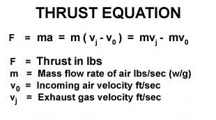
The rest of the air is mixed with the products of combustion for cooling before the gases enter the turbine wheel . The turbine extracts a major portion of energy in the gas stream and uses this energy to turn the compressor and accessories . The engine's thrust comes from taking a large mass of air in at the front and expelling it at a much higher speed than it had when it entered the compressor . THRUST , THEN , IS EQUAL TO MASS FLOW RATE TIMES CHANGE IN VELOCITY .
The more air that an engine can compress and use , the greater is the power or thrust that it can produce . Roughly 75% of the power generated inside a jet engine is used to drive the compressor . Only what is left over is available to produce the thrust needed to propel the airplane .
JET ENGINE EQUATION
Since Fuel flow adds some mass to the air flowing through the engine , this must be added to the basic of thrust equation . Some formular do not consider the fuel flow effect when computing thrust because the weight of air leakage is approximately equal to the weight of fuel added .
The following formular is applied when a nozzle of engine is " choked " , the pressure is such that the gases are treveling through it at the speed of sound and can not be further accelerated . Any increase in internal engine pressure will pass out through the nozzle still in the form of pressure .
Even this pressure energy cannot turn into velocity energy but it is not lost .
FACTORS AFFECTINGTHRUST
The Jet engine is much more sensitive to operating variables . Those are:
1.) Engine rpm. 2.) Size of nozzle area. 3.) Weight of fuel flow. 4.) Amount of air bled from the compressor. 5.) Turbine inlet temperature. 6.) Speed of aircraft (ram pressure rise). 7.) Temperature of the air. 8.) Pressure of air 9.) Amount of humidity. Note ; item 8,9 are the density of air .
ENGINE STATION DESIGNATIONS
Station designations are assigned to the varius sections of gas turbine engines to enable specific locations within the engine to be easily and accurately identified.
The station numbers coincide with position from front to rear of the engine and are used as subscripts when designating different temperatures and pressures at the front , rear , or inside of the engine.
For engine configurations other than the picture below should be made to manuals published by the engine manufacturer. N = Speed ( rpm or percent ) N1 = Low Compressor Speed N2 = High Compressor Speed N3 = Free Turbine Speed P = Pressure T = Temperature t = Total EGT = Exhaust Gas Temperature EPR = Engine Pressure Ratio ( Engine Thrust in term of EPR ). Pt7 / Pt2 Ex.: Pt 2 = Total Pressure at Station 2 ( low pressure compressor inlet ) Pt 7 = Total Pressure at Station 7 ( turbine discharge total pressure )
ENGINE CONSTRUCTION
AIR INLET DUCT
An engine's air inlet duct is normally considered an airframe part and made by aircraft manufacturer . During flight operation , it is very important to the engine performance . Engine thrust can be high only if the inlet duct supplies the engine with the required airflow at the highest posible pressure
The inlet duct has two engine functions and one aircraft function .
First : it must be able recover as much of the total pressure of the free air stream as posible and deliver this pressure to the front of the engine compressor .
Second : the duct must deliver air to the compressor under all flight conditions with a little turbulance
Third : the aircraft is concerned , the duct must hold to a minimum of the drag.
The duct also usually has a diffusion section just ahead of the compressor to change the ram air velocity into higher static pressure at the face of the engine . This is called ram recovery . The inlet duct is built generally in the divergent shape (subsonic diffuser).
Supersonic Duct
The supersonic duct proplems start when the aircraft begins to fly at or near the speed of sound. At this speeds sonic shock waves are developed which , if not controlled , will give high duct loss in pressure and airflow , and will set up vibrating conditions in the inlet duct called inlet " buzz " .
Buzz is an airflow instability caused by the shock wave rapidly being alternately swallowed and expelled at the inlet of the duct. Air enters the compressor section of engine must be slow to subsonic velocity.
At supersonic speeds the inlet does the job by slowing the air with minimize energy loss and the temperature rise.
At transonic speeds the inlet duct is designed to keep shock waves out of the duct. This is done by locating the inlet duct behind a spike or probe which create the shock wave infront of inlet duct. This normal shock wave will produce a pressure rise and velocity decrease to subsonic speeds .
At higher mach numbers, the single normal shock wave is very strong and causes a great reduction in the total pressure recoverd by the duct and excessive air temperature rise inside the duct.
The oblique shock wave will be used to slow the supersonic velocity down but still supersonic , the normal shock wave will drop the velocity to subsonic before the air enter to the compressor. Each reduce in velocity will increase a pressure. At very high mach number , the inlet duct must set up one or moreoblique shocks and a normal shock.
COMPRESSOR
The combustion of fuel and air at normal atmospheric pressure will not produce sufficient energy enough to produce useful work . The energy released by combustion is proportional to the mass of air consumed and its pressure.
Therefore , higher pressure are needed to increase the efficiency of the combustion cycle . On the jet engines must rely upon some other means of compression .
Although centrifugal compressors are used in many jet engine , the efficiency level of a single stage is relatively low . The multistage of centrifugal compressor is better , but still do not compare with those axial flow compressors .
Some small modern turboshaft and turboprop engines achieve good results by using a combination of axial flow and centrifugal compressor.
Centrifugal compressor
Centrifugal compressors operate by taking in outside air near their hub and rotating it by means of an impeller . The impeller , which is usually an aluminum alloy , guides the air toward the outer circumference of the compressor , building up the velocity of the air by means of high rotational speed of the impeller .
The compressor consists of three main parts:
1) Impeller 2) A Diffuser 3) A Comprssor Manifold
Air leaves the Impeller at high speed , and flows through the diffuser which converts high velocity , kinetic energy to low velocity , high pressure energy . The diffuser also serves to direct airflow to the compressor manifold which acts as collector ring. They also delivery air to the manifold at a velocity and pressure which will be satisfactory for use in the burner section of the engine.
Axial compressor
The air in an axial compressor flows in an axial direction through a series of rotating rotor blades and stationary stator vanes. The flow path of an axial compressor decreases in cross-section area in the direction of flow , reducing the volume of the air as compression progresses from stage to stage of compressor blades .
The air being delivered to the face of compressor by the air inlet duct, the incoming air passes through the inlet guide vanes . Air upon entering the first set of ratating blades and flowing in axial direction, is deflected in the direction of rotation . The air is arrested and turn as it is passed on to a set of stator vanes , following which it is again picked up by another set of rotating blades , and so on , through the compressor . The pressure of the air increases each time that it passes through a set of rotors and stators .
The aerodynamic principles are applied to the compressor blade design in order to increase efficiency . The blades are treated as lifting surfaces like aircraft wings or propeller blades . The cascade effect is a primary consideration in determining the airfoil section , angle of attack , and the spacing between blades to be used for compressor blade disign . The blade must be designed to withstand the high centrifugal forces as well as the aerodynamic loads to which they are subjected . The clearance between the rotating blades and their outer case is also very important . The rotor assembly turns at extreamely high speed , and must be rigid , well aligned and well balance .
Compressor Surge and Compressor Stall
This characteristic has been called both " Surge " and " Stall " in the past , but is more properly called SURGE when it is response of the entire engine. The word stall applies to the action occuring at each individual compressor blade. Compressor surge , also called Compressor stall , is a phenomenon which is difficult to understand because it is usually caused by complex combination of factors . The basic cause of compressor surge is fairly simple , each blade in an axial flow compressor is a miniature airplane wing which , when subjected to a higher angle of attack , will stall just as an airplane stalls. Surge may define as results from an unstable air condition within the compressor. Pilot or engine operator has no instrument to tell him that one or more blades are stalling. He must wait until the engine surges to know that. The unstable condition of air is often caused from air piling up in the rear stages of the compressor. Surge may become sufficiently pronounce to cause lound bangs and engine vibration. In most case , this condition is of short duration , and will either correct itself or can be corrected by retarding the throttle or power lever to Idle and advanncing it again , slowly. Among other things , to minimize the tendency of a compressor to surge , the compressor can be "unload" during certain operating conditions by reducing the pressure ratio across the compressor for any giving airflow. One method of doing this is by bleeding air from the middle or toward the rear of the compressor. In dual axial compressor engines , air is often bled from between the low and the high pressure compressor. Air bleed ports are located in the compressor section. These ports are fitted with automatic , overboard bleed valves which usually operate in a specified range of engine RPM. Some large engine have been provided with variable-angle stators ( variable stators) in a few of the forward compressor stages. The angle of these vanes change automatically to prevent the choking of the downstream compressor stages as engine operating conditions vary.
Turbofan Fan Section
They are considered as part of the compressor section in dual axial flow compressor engines because the fan is formed by the outer part of the front stages of the low compressor. The fan also seperate from the forward compressor and is driven by a freely rotating turbine of it own. The forward fan design is now used by most of engine manufacturers. In dual compressor engines , the fan is often integral with the relatively slow turning low compressor , which allows the fan blades to rotate at low tip speed.
DIFFUSER SECTION
The diffuser has an expanding internal diameter to decrease the velocity and increase the static pressure of air . The air leaving compressor , then through a diffuser section . The diffuser prepares the air for entry the combustion section at low velocity to permit proper mixing with fuel . Ports are built in the diffuser case through which compressor discharge air is bled off from the aircraft engine .
On dual compressor engines , bleed air for service functions is also taken from additional ports located between the low and high compressors , or at intermediate stages in the high pressure compressor case . Air is bled from most engine vented over board out of the primary air flow path during certain engine operating conditions to prevent compressor surge . This is called over board and must not be confused with the air remove from the engine to perform service function .
FUEL MANIFOLDS and NOZZLES
Fuel is introduced into the air stream at the front of the burners in spray form , suitable for rapid mixing with air for combustion. The fuel is carried from outside the engine , by manifold system , to nozzles mounted in the burner cans .
Primary and secondary fuel manifolds are often used on large engines . The primary manifold provides sufficient fuel for low thrust operation. At high thrust , the secondary , or main manifold cuts in , and fuel commences to flow through both primary and secondary elements of double-orifice nozzle. Usually , primary fuel is sprayed through a single orifice at the center of nozzle. Secondary fuel is sprayed through a number of orifices in a ring around the center orifice.
COMBUSTION CHAMBERS OR BURNER SECTION
There are three basic types of burner systems in use today. They are can type , annular type and can-annular type. Fuel is introduced at the front end of the burner. Air flows in around the fuel nozzle and through the first row of combustion air holes in the liner. The air entering the forward section of the liner tends to recirculate and move up stream against the fuel spray. During combustion , this action permits rapid mixing and prevents flame blowout which acts as a continuous pilot for the rest of the burner.
There are usually has only two igniter plugs in an engine. The igniter plug is usually locate in the up stream region of the burner. About 25 percent of the air actually takes part in the combustion process. The gases that result from the combustion have temperatures of 3500 degree F. Before entering the turbine , the gases must be cooled to approximately half this value , up to the designed of turbine materials involved. Cooling is done by diluting the hot gases with secondary air that enters through a set of relative large holes located toward the rear of the liner.
TURBINE SECTION
The turbine in all modern jet engines , regardless of the type of compressor used , are of axial flow design.
The turbine extract kinetic energy from the expanding gases as the gases come from the burner , converting this energy into shaft horsepower to drive the compressor and the engine accessory. Nearly three fourths of all energy available from the product of combustion is needed to drive the compressors.
The turbine wheel is one of the most highly stressed parts in the engine. Not only must it operateat temperature 1700 degree F, but it must do so under severe centrifugal loads imposed by high rotational speeds of over 40000 rpm for small engines to 8000 rpm for a larger engines. The engine speed and turbine inlet temperature must be accurately controlled to keep the turbine within safe operating limits. The turbine assembly is made of two main parts , the disk and the blades. The disk or wheel is statically and dynamically balanced and unit specially alloyed steel usually containing large percentages of chromium , nickle , and cobalt. The blades are attached to the disk by means of a " fir tree " design to allow for different rates of expansion between the disk and the blade while still holding the blade firmly against centrifugal loads. The blade is kept from moving axially either by rivets , special locking tabs or devices , or another turbine stage.
The blade is shrouded at the tip. The shrouded blades form a band around the perimeter of the turbine which serves to reduce blade vibrations. The shrouds improve the airflow characteristics and increase the efficiency of the turbine. The shrouds also serve to cut down gas leakage around the tips of the turbine blades.
EXHAUST DUCT OR EXHAUST PIPE
larger total thrust can be obtained from the engine if the gases are discharged from the aircraft at a higher velocity than is permissible at the turbine outlet. An exhaust duct is therefore added , both to collect and straighten the gas flow as it comes from the turbine and to increase the velocity of the gases before they are discharged from the exhaust nozzle at the rear of the duct.
Increasing the velocity of the gases increases their momentum and increase the thrust produced.The duct is essentially a simple , stainless steel , conical or cylinder pipe .
The tail cone helps smooth the flow. A conventional convergent type of exhaust duct is capable of keeping the flow through the duct constant at velocity not to exceed Mach 1.0 at the exhaust nozzle.
AFTER BURNING
The afterburner , whose operation is much like a ram-jet , increases thrust by adding fuel to the exhaust gases after they have passed through the turbine section. At this point there is still much uncombined oxygen in the exhaust. Only approximately 25 percent of the air passing through the engine is consumed by the combustion. The remainder or 75 percent , of the air is capable of supporting additional combustion if more fuel is added. The resultant increase in the temperature and velocity of gases therefore boosts engine thrust. Most afterburners will produce an approximately 50 percent more thrust. Afterburning or " hot " operation or " reheating " is used only for a time limited operation of takeoff , climb , and maximum burst speed.