AIRCRAFT GAS TURBINE ENGINES
The name GAS TURBINE means exactly what it says. A turbine type engine that is operated by gas rather than one operated, for instance, by steam or water. The gas which operates the turbine is the product of the combustion that take place when a suitable fuel is mixed and burned with the air passing through the engine.
Leonado Da Vinci
 Da Vinci described the chimney jack, as the hot air from the fire rose, it was made to pass through a series of fan blades and through a series of gears, turn a roasting.
Sir Isaac Newton
 Sir Isaac Newton formulated the laws of MOTION on which all devices utilizing the jet propulsion theory are based.
 The vehicle illustrated in the picture below , called Newton's wagon , applied the principle of jet propulsion .
It is though that Jacob Gravesand , a Dutchman , actually designed this " horseless carriage", and that Isaac Newton may have only supplied the idea. The wagon consisted of a large boiler mounted on four wheels.
Steam generated by fire built below the boiler was allowed to escape through a nozzle facing rearward. The speed of vehicle was controlled by a steam cock located in the nozzle.
 HISTORY
England
Sir Frank Whittle :
Whittle is considered by many to be the father of the jet engine. In 1930 Frank Whittle submitted his patent application for a jet aircraft engine.


Germany
VON OHAIN
 At the same time, von Ohain in Germany had been at work on the development of a jet engine for aircraft.
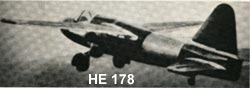
 He built and ran his first demonstration engine in 1937. His first flight engine was the HES 3B which used on HE178 and flew on August 27,1939.
 The Whittle and the von Ohain engines led to successful jet-powered fighter aircraft by the end of World War II , the Messerschmitt Me262 that was used by German Air Force.
It might be note that the early English production jet engine used centrifugal compressor where as the production engine in Germany employed the more advanced axial flow compressor.
America

The first jet engine airplane in America was made in October 1942, in Bell XP-59A .
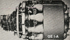 The two General Electric I-A engines used in this airplane, the I-A engine was rated at about 1300 lb of thrust.
In late 1941 , NAVY awarded the contract to Westinghouse . Westinghouse engineers designed an engine with an axial compressor and an anular combustion chamber.
Shortly thereafter, several other companies began to design and produce gas turbine engines.
ENGINE TYPES and APPLICATIONS
Introduction
Most of modern passenger and military aircraft are powered by gas turbine engines, which are also called jet engines. There are several types of jet engines, but all jet engines have some parts in common . Aircraft gas turbine engines can be classified according to (1) the type of compressor used and (2) power usage produces by the engine.
Compressor types are as follows 1. Centrifugal flow
2. Axial flow
3. Centrifugal-Axial flow.
Power usage produced are as follows 1. Turbojet engines
2. Turbofan engines.
3. Turboshaft engines.
Centrifugal Compressor Engines
Centrifugal flow engines are compress the air by accelerating air outward perpendicular to the longitudinal axis of the machine. Centrifugal compressor engines are divided into Single-Stage and Two-Stage compressor. The amount of thrust is limited because the maximum compression ratio.


Principal Advantages of Centrifugal Compressor
1. Light Weight
2. Simplicity
3. Low cost.
2. Simplicity
3. Low cost.
Axial Flow Compressor Engines


 Axial flow compressor engines may incorporate one , two , or three spools (Spool is defined as a group of compressor stages rotating at the same speed) . Two spool engine , the two rotors operate independently of one another. The turbine assembly for the low pressure compressor is the rear turbine unit . This set of turbines is connected to the forward , low pressure compressor by a shaft that passes through the hollow center of the high pressure compressor and turbine drive
 Adventages and Disadventages
Adventages:
Most of the larger turbine engines use this type of compressor because of its ability to handle large volumes of airflow and high pressure ratio.
Disadventages:
Disadventages:
More susceptable to foreign object damage , Expensive to manufacture , and It is very heavy in comparision to the centrifugal compressor with the same compression ratio.
Axial-Centrifugal Compressor Engine
 Centrifugal compressor engine were used in many early jet engines , the efficiency level of single stage centrifugal compressor is relatively low .
The multi-stage compressors are some what better , but still do not match with axial flow compressors.
. Some small modern turbo-prop and turbo-shaft engines achieve good results by using a combination axial flow and centrifugal compressor such as PT6 Pratt and Whitney of canada which very popular in the market today and T53 Lycoming engine.
Characteristics and Applications

The turbojet engine :
Turbojet engine derives its thrust by highly accelerating a mass of air , all of which goes through the engine.
Since a high " jet " velocity is required to obtain an acceptable of thrust, the turbine of turbo jet is designed to extract only enough power from the hot gas stream to drive the compressor and accessories .
All of the propulsive force (100% of thrust ) produced by a jet engine derived from exhaust gas.
The turboprop engine :
Turboprop engine derives its propulsion by the conversion of the majority of gas stream energy into mechanical power to drive the compressor , accessories , and the propeller load.
The shaft on which the turbine is mounted drives the propeller through the propeller reduction gear system .
Approximately 90% of thrust comes from propeller and about only 10% comes from exhaust gas.
The turbofan engine :
Turbofan engine has a duct enclosed fan mounted at the front of the engine and driven either mechanically at the same speed as the compressor , or by an independent turbine located to the rear of the compressor drive turbine
.
.
The fan air can exit seperately from the primary engine air , or it can be ducted back to mix with the primary's air at the rear .
. Approximately morethan 75% of thrust comes from fan and less than 25% comes from exhaust gas.
The turboshaft engine :
Turboshaft engine derives its propulsion by the conversion of the majority of gas stream energy into mechanical power to drive the compressor , accessories , just like the turboprop engine
but The shaft on which the turbine is mounted drives something other than an aircraft propeller such as the rotor of a helicopter through the reduction gearbox .
The engine is called turboshaft.
ENGINE THEORY
OPERATION
 The jet engines are essentially a machine designed for the purpose of producing high velocity gasses at the jet nozzle .
The engine is started by rotating the compressor with the starter , the outside air enter to the engine .
The compressor works on this incoming air and delivery it to the combustion or burner section with as much as 12 times or more pressure the air had at the front .
At the burner or combustion section , the ignition is igniting the mixture of fuel and air in the combustion chamber with one or more igniters which somewhat likes automobile spark plugs. When the engine has started and its compressor is rotating at sufficient speed , the starter and igniters are turn off.
The engine will then run without further assistance as long as fuel and air in the proper proportions continue to enter the combustion chamber. Only 25% of the air is taking part in the actual combustion process .
The engine will then run without further assistance as long as fuel and air in the proper proportions continue to enter the combustion chamber. Only 25% of the air is taking part in the actual combustion process .
The rest of the air is mixed with the products of combustion for cooling before the gases enter the turbine wheel . The turbine extracts a major portion of energy in the gas stream and uses this energy to turn the compressor and accessories .
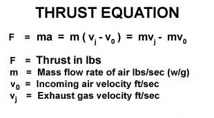
The engine's thrust comes from taking a large mass of air in at the front and expelling it at a much higher speed than it had when it entered the compressor . THRUST , THEN , IS EQUAL TO MASS FLOW RATE TIMES CHANGE IN VELOCITY .
The engine's thrust comes from taking a large mass of air in at the front and expelling it at a much higher speed than it had when it entered the compressor . THRUST , THEN , IS EQUAL TO MASS FLOW RATE TIMES CHANGE IN VELOCITY .
The more air that an engine can compress and use , the greater is the power or thrust that it can produce . Roughly 75% of the power generated inside a jet engine is used to drive the compressor . Only what is left over is available to produce the thrust needed to propel the airplane .
JET ENGINE EQUATION
Since Fuel flow adds some mass to the air flowing through the engine , this must be added to the basic of thrust equation .
Some formular do not consider the fuel flow effect when computing thrust because the weight of air leakage is approximately equal to the weight of fuel added .
Some formular do not consider the fuel flow effect when computing thrust because the weight of air leakage is approximately equal to the weight of fuel added .
 The following formular is applied when a nozzle of engine is " choked " , the pressure is such that the gases are treveling through it at the speed of sound and can not be further accelerated .
 Any increase in internal engine pressure will pass out through the nozzle still in the form of pressure .
Even this pressure energy cannot turn into velocity energy but it is not lost .
FACTORS AFFECTINGTHRUST
The Jet engine is much more sensitive to operating variables . Those are:
1.) Engine rpm.
2.) Size of nozzle area.
3.) Weight of fuel flow.
4.) Amount of air bled from the compressor.
5.) Turbine inlet temperature.
6.) Speed of aircraft (ram pressure rise).
7.) Temperature of the air.
8.) Pressure of air
9.) Amount of humidity.
Note ; item 8,9 are the density of air .
2.) Size of nozzle area.
3.) Weight of fuel flow.
4.) Amount of air bled from the compressor.
5.) Turbine inlet temperature.
6.) Speed of aircraft (ram pressure rise).
7.) Temperature of the air.
8.) Pressure of air
9.) Amount of humidity.
Note ; item 8,9 are the density of air .
ENGINE STATION DESIGNATIONS

The station numbers coincide with position from front to rear of the engine and are used as subscripts when designating different temperatures and pressures at the front , rear , or inside of the engine.
For engine configurations other than the picture below should be made to manuals published by the engine manufacturer.
N = Speed ( rpm or percent )
N1 = Low Compressor Speed
N2 = High Compressor Speed
N3 = Free Turbine Speed
P = Pressure
T = Temperature
t = Total
EGT = Exhaust Gas Temperature
EPR = Engine Pressure Ratio ( Engine Thrust in term of EPR ). Pt7 / Pt2
Ex.: Pt 2 = Total Pressure at Station 2 ( low pressure compressor inlet )
Pt 7 = Total Pressure at Station 7 ( turbine discharge total pressure )
ENGINE CONSTRUCTION
AIR INLET DUCT

. Engine thrust can be high only if the inlet duct supplies the engine with the required airflow at the highest posible pressure
The inlet duct has two engine functions and one aircraft function .
First : it must be able recover as much of the total pressure of the free air stream as posible and deliver this pressure to the front of the engine compressor .
Second : the duct must deliver air to the compressor under all flight conditions with a little turbulance
Third : the aircraft is concerned , the duct must hold to a minimum of the drag.
The duct also usually has a diffusion section just ahead of the compressor to change the ram air velocity into higher static pressure at the face of the engine . This is called ram recovery . The inlet duct is built generally in the divergent shape (subsonic diffuser).
Supersonic Duct
 The supersonic duct proplems start when the aircraft begins to fly at or near the speed of sound.
 At this speeds sonic shock waves are developed which , if not controlled , will give high duct loss in pressure and airflow , and will set up vibrating conditions in the inlet duct called inlet " buzz " .
Buzz is an airflow instability caused by the shock wave rapidly being alternately swallowed and expelled at the inlet of the duct. Air enters the compressor section of engine must be slow to subsonic velocity.
At supersonic speeds the inlet does the job by slowing the air with minimize energy loss and the temperature rise.
At transonic speeds the inlet duct is designed to keep shock waves out of the duct. This is done by locating the inlet duct behind a spike or probe which create the shock wave infront of inlet duct. This normal shock wave will produce a pressure rise and velocity decrease to subsonic speeds .
At higher mach numbers, the single normal shock wave is very strong and causes a great reduction in the total pressure recoverd by the duct and excessive air temperature rise inside the duct.
The oblique shock wave will be used to slow the supersonic velocity down but still supersonic , the normal shock wave will drop the velocity to subsonic before the air enter to the compressor. Each reduce in velocity will increase a pressure.
At very high mach number , the inlet duct must set up one or moreoblique shocks and a normal shock.
At very high mach number , the inlet duct must set up one or moreoblique shocks and a normal shock.
COMPRESSOR
 The combustion of fuel and air at normal atmospheric pressure will not produce sufficient energy enough to produce useful work .
The energy released by combustion is proportional to the mass of air consumed and its pressure.
Therefore , higher pressure are needed to increase the efficiency of the combustion cycle . On the jet engines must rely upon some other means of compression .
Although centrifugal compressors are used in many jet engine , the efficiency level of a single stage is relatively low . The multistage of centrifugal compressor is better , but still do not compare with those axial flow compressors .
Some small modern turboshaft and turboprop engines achieve good results by using a combination of axial flow and centrifugal compressor.
Centrifugal compressor
Centrifugal compressors operate by taking in outside air near their hub and rotating it by means of an impeller . The impeller , which is usually an aluminum alloy , guides the air toward the outer circumference of the compressor , building up the velocity of the air by means of high rotational speed of the impeller .
The compressor consists of three main parts:
1) Impeller
2) A Diffuser
3) A Comprssor Manifold
2) A Diffuser
3) A Comprssor Manifold
 Air leaves the Impeller at high speed , and flows through the diffuser which converts high velocity , kinetic energy to low velocity , high pressure energy .
The diffuser also serves to direct airflow to the compressor manifold which acts as collector ring. They also delivery air to the manifold at a velocity and pressure which will be satisfactory for use in the burner section of the engine.
Axial compressor

The flow path of an axial compressor decreases in cross-section area in the direction of flow , reducing the volume of the air as compression progresses from stage to stage of compressor blades .
 The air being delivered to the face of compressor by the air inlet duct, the incoming air passes through the inlet guide vanes .
Air upon entering the first set of ratating blades and flowing in axial direction, is deflected in the direction of rotation .
The air is arrested and turn as it is passed on to a set of stator vanes , following which it is again picked up by another set of rotating blades , and so on , through the compressor . The pressure of the air increases each time that it passes through a set of rotors and stators .
The aerodynamic principles are applied to the compressor blade design in order to increase efficiency . The blades are treated as lifting surfaces like aircraft wings or propeller blades . The cascade effect is a primary consideration in determining the airfoil section , angle of attack , and the spacing between blades to be used for compressor blade disign .
The blade must be designed to withstand the high centrifugal forces as well as the aerodynamic loads to which they are subjected . The clearance between the rotating blades and their outer case is also very important .
The rotor assembly turns at extreamely high speed , and must be rigid , well aligned and well balance .
Compressor Surge and Compressor Stall
This characteristic has been called both " Surge " and " Stall " in the past , but is more properly called SURGE when it is response of the entire engine. The word stall applies to the action occuring at each individual compressor blade. Compressor surge , also called Compressor stall , is a phenomenon which is difficult to understand because it is usually caused by complex combination of factors .
The basic cause of compressor surge is fairly simple , each blade in an axial flow compressor is a miniature airplane wing which , when subjected to a higher angle of attack , will stall just as an airplane stalls. Surge may define as results from an unstable air condition within the compressor.
Pilot or engine operator has no instrument to tell him that one or more blades are stalling. He must wait until the engine surges to know that. The unstable condition of air is often caused from air piling up in the rear stages of the compressor. Surge may become sufficiently pronounce to cause lound bangs and engine vibration. In most case , this condition is of short duration , and will either correct itself or can be corrected by retarding the throttle or power lever to Idle and advanncing it again , slowly.
Among other things , to minimize the tendency of a compressor to surge , the compressor can be "unload" during certain operating conditions by reducing the pressure ratio across the compressor for any giving airflow. One method of doing this is by bleeding air from the middle or toward the rear of the compressor.
In dual axial compressor engines , air is often bled from between the low and the high pressure compressor. Air bleed ports are located in the compressor section. These ports are fitted with automatic , overboard bleed valves which usually operate in a specified range of engine RPM.
Some large engine have been provided with variable-angle stators ( variable stators) in a few of the forward compressor stages. The angle of these vanes change automatically to prevent the choking of the downstream compressor stages as engine operating conditions vary.
Turbofan Fan Section
 They are considered as part of the compressor section in dual axial flow compressor engines because the fan is formed by the outer part of the front stages of the low compressor.
The fan also seperate from the forward compressor and is driven by a freely rotating turbine of it own.
The forward fan design is now used by most of engine manufacturers. In dual compressor engines , the fan is often integral with the relatively slow turning low compressor , which allows the fan blades to rotate at low tip speed.
DIFFUSER SECTION
 The diffuser has an expanding internal diameter to decrease the velocity and increase the static pressure of air .
The air leaving compressor , then through a diffuser section . The diffuser prepares the air for entry the combustion section at low velocity to permit proper mixing with fuel .
Ports are built in the diffuser case through which compressor discharge air is bled off from the aircraft engine .
 On dual compressor engines , bleed air for service functions is also taken from additional ports located between the low and high compressors , or at intermediate stages in the high pressure compressor case .
Air is bled from most engine vented over board out of the primary air flow path during certain engine operating conditions to prevent compressor surge .
This is called over board and must not be confused with the air remove from the engine to perform service function .
FUEL MANIFOLDS and NOZZLES
Fuel is introduced into the air stream at the front of the burners in spray form , suitable for rapid mixing with air for combustion. The fuel is carried from outside the engine , by manifold system , to nozzles mounted in the burner cans .
 Primary and secondary fuel manifolds are often used on large engines .
The primary manifold provides sufficient fuel for low thrust operation.
At high thrust , the secondary , or main manifold cuts in , and fuel commences to flow through both primary and secondary elements of double-orifice nozzle. Usually , primary fuel is sprayed through a single orifice at the center of nozzle. Secondary fuel is sprayed through a number of orifices in a ring around the center orifice.
COMBUSTION CHAMBERS OR BURNER SECTION

The air entering the forward section of the liner tends to recirculate and move up stream against the fuel spray. During combustion , this action permits rapid mixing and prevents flame blowout which acts as a continuous pilot for the rest of the burner.
There are usually has only two igniter plugs in an engine. The igniter plug is usually locate in the up stream region of the burner. About 25 percent of the air actually takes part in the combustion process.
The gases that result from the combustion have temperatures of 3500 degree F. Before entering the turbine , the gases must be cooled to approximately half this value , up to the designed of turbine materials involved.
Cooling is done by diluting the hot gases with secondary air that enters through a set of relative large holes located toward the rear of the liner.


TURBINE SECTION
 The turbine in all modern jet engines , regardless of the type of compressor used , are of axial flow design.
The turbine extract kinetic energy from the expanding gases as the gases come from the burner , converting this energy into shaft horsepower to drive the compressor and the engine accessory.
Nearly three fourths of all energy available from the product of combustion is needed to drive the compressors.
Nearly three fourths of all energy available from the product of combustion is needed to drive the compressors.
 The turbine wheel is one of the most highly stressed parts in the engine.
 Not only must it operateat temperature 1700 degree F, but it must do so under severe centrifugal loads imposed by high rotational speeds of over 40000 rpm for small engines to 8000 rpm for a larger engines.
The engine speed and turbine inlet temperature must be accurately controlled to keep the turbine within safe operating limits.
The turbine assembly is made of two main parts , the disk and the blades. The disk or wheel is statically and dynamically balanced and unit specially alloyed steel usually containing large percentages of chromium , nickle , and cobalt.
The blades are attached to the disk by means of a " fir tree " design to allow for different rates of expansion between the disk and the blade while still holding the blade firmly against centrifugal loads.
The blade is kept from moving axially either by rivets , special locking tabs or devices , or another turbine stage.

The blade is shrouded at the tip. The shrouded blades form a band around the perimeter of the turbine which serves to reduce blade vibrations. The shrouds improve the airflow characteristics and increase the efficiency of the turbine. The shrouds also serve to cut down gas leakage around the tips of the turbine blades.
EXHAUST DUCT OR EXHAUST PIPE
 larger total thrust can be obtained from the engine if the gases are discharged from the aircraft at a higher velocity than is permissible at the turbine outlet.
 An exhaust duct is therefore added , both to collect and straighten the gas flow as it comes from the turbine and to increase the velocity of the gases before they are discharged from the exhaust nozzle at the rear of the duct.
 Increasing the velocity of the gases increases their momentum and increase the thrust produced.The duct is essentially a simple , stainless steel , conical or cylinder pipe .
The tail cone helps smooth the flow. A conventional convergent type of exhaust duct is capable of keeping the flow through the duct constant at velocity not to exceed Mach 1.0 at the exhaust nozzle.
AFTER BURNING
 The afterburner , whose operation is much like a ram-jet , increases thrust by adding fuel to the exhaust gases after they have passed through the turbine section.
At this point there is still much uncombined oxygen in the exhaust. Only approximately 25 percent of the air passing through the engine is consumed by the combustion.
The remainder or 75 percent , of the air is capable of supporting additional combustion if more fuel is added. The resultant increase in the temperature and velocity of gases therefore boosts engine thrust. Most afterburners will produce an approximately 50 percent more thrust.
Afterburning or " hot " operation or " reheating " is used only for a time limited operation of takeoff , climb , and maximum burst speed.
No comments:
Post a Comment